 English
 Espaol
 Franais
 阿拉伯
阿拉伯 中文(簡)
中文(簡) Deutsch
 Italiano
 Português
 日本
日本 韓國
韓國 български
 hrvatski
 esky
esky Dansk
Dansk Nederlands
 suomi
suomi Ελληνικ
 印度
印度 norsk
norsk Polski
 Roman
Roman русский
 Svenska
 Perkins珀金斯100維修手冊,Perkins珀金斯100維修手冊技術支持中心,Perkins珀金斯100維修手冊代理商,Perkins珀金斯100維修手冊銷售服務中心,Perkins珀金斯100維修手冊價格規格資料查詢,寧波日昕動力科技有限公司

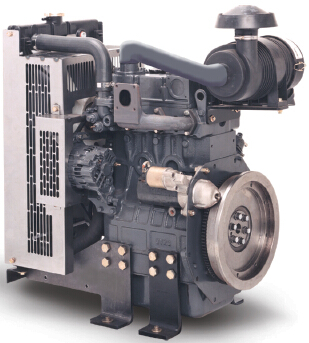
Perkins珀金斯100維修手冊(英文)
詳細描述
Perkins 100 Series
Models 102-05, 103-07, 103-10, 103-13, 103-15, 104-19,
104-22
WORKSHOP MANUAL
102-05
Two cylinder diesel engines
Three cylinder diesel engines
103-07
103-10
103-13
103-15
104-19
104-22
Four cylinder diesel engines
Publication TPD 1377E, Issue 4
© Proprietary information of Perkins Engines Company Limited, all rights reserved.
The information is correct at the time of print.
Published in September 2003 by Technical Publications.
i
This document has been printed from SPI². Not for Resale
![]()
![]()
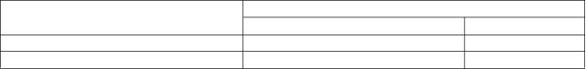
To inspect
Operation 3-16
Special requirements
Free length (A3) mm (in)
Engine model
Standard
Service limit
31,5 (1.240)
33,5 (1.319)
102-05, 103-07
33,0 (1.299)
35,0 (1.378)
103-10, 103-13, 103-15, 104-19, 104-22
Spring rate when compressed to
30,4 mm (1.197 in) N (lbf) kgf
Engine model
Standard
Service limit
102-05, 103-07
68 (15.2) 6,9
79 (17.9) 8,1
59 (13.2) 6,0
69 (15.4) 7,0
103-10, 103-13, 103-15, 104-19, 104-22
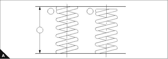
1 Visually inspect the valve spring for damage. A new spring (A1) and a worn spring (A2) are shown.
2 Using a spring tester, check spring force and free length. Renew if found to be beyond the service limit.
1
2
3
40
Workshop Manual, TPD 1377E, issue 4
This document has been printed from SPI². Not for Resale
![]()
![]()
![]()
![]()

3
100 Series
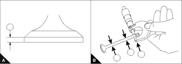
Valve stem diameter and thickness of valve head
To inspect
Operation 3-17
Valve head thickness
If the valve head thickness is less than the service limit, renew the valve.
Thickness (A1) mm (in)
Standard
Service limit
0,925 - 1,075 (0.03642 - 0.04232)
0,5 (0,020) max
Valve stem diameter
Check the valve stem for excessive wear or damage. If found to be excessively worn or damaged, renew the
valve.
Check the valve stem diameters at positions (B1), (B2) and (B3) with a micrometer. If the diameter is less than
the service limit, renew the valve.
Intake valve
Diameter mm (in)
Engine model
Standard
Service limit
5,9 (0.232)
102-05, 103-07
5,960 - 5,975 (0.23464 - 0.23524)
6,955 - 6,970 (0.27382 - 0.27441)
103-10, 103-13, 103-15, 104-19, 104-22
6,89 (0.271)
Exhaust valve
Engine model
Diameter mm (in)
Standard
Service limit
5,9 (0.232)
102-05, 103-07
5,940 - 5,955 (0.23386 - 0.23445)
6,940 - 6,950 (0.27323 - 0.27362)
103-10, 103-13, 103-15, 104-19, 104-22
6,84 (0.269)
1
2
1
3
Workshop Manual, TPD 1377E, issue 4
41
This document has been printed from SPI². Not for Resale
![]()
![]()
![]()
![]()

3
100 Series
Valve guide clearance
To inspect
Operation 3-18
Check the clearance between the valve and valve-guide.
If the clearance exceeds the service limit, renew the cylinder head.
Intake valve
Clearance (A1) mm (in)
Engine model
Standard
Service limit
0,2 (0.008) max
0,2 (0.008) max
102-05, 103-07, 103-10
0,025 - 0,052 (0.001 - 0.002)
103-13, 103-15, 104-19, 104-22
0,03 - 0,06 (0.0012 - 0.0024)
Exhaust valve
Engine model
Clearance (A1) mm (in)
Standard
0,045 - 0,072 (0.0018 - 0.0028)
0,05 - 0,075 (0.002 - 0.003)
Service limit
0,25 (0.010) max
0,25 (0.010) max
102-05, 103-07, 103-10
103-13, 103-15, 104-19, 104-22
1
42
Workshop Manual, TPD 1377E, issue 4
This document has been printed from SPI². Not for Resale
![]()
![]()
![]()
![]()


3
100 Series
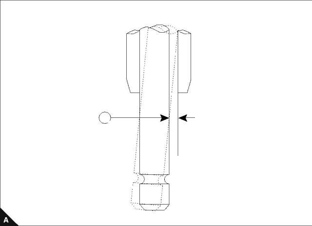
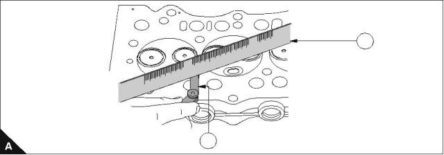
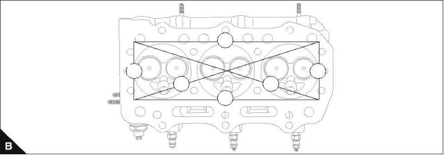
Cylinder head
To check the distortion of the lower face
Operation 3-19
Special requirements
Maximum machine limit mm (in)
Distortion
Max service limit
Max regrind
0,05 (0.002) OR LESS
0,12 (0.005)
0,15 (0.006)
Using a straight edge (A1) and feeler gauge (A2) check the six positions (lines B1 to B6) for distortion. Do not
machine beyond the maximum limit.
1
2
1
3
4
5
6
2
Workshop Manual, TPD 1377E, issue 4
43
This document has been printed from SPI². Not for Resale
![]()
![]()
![]()
![]()

3
100 Series
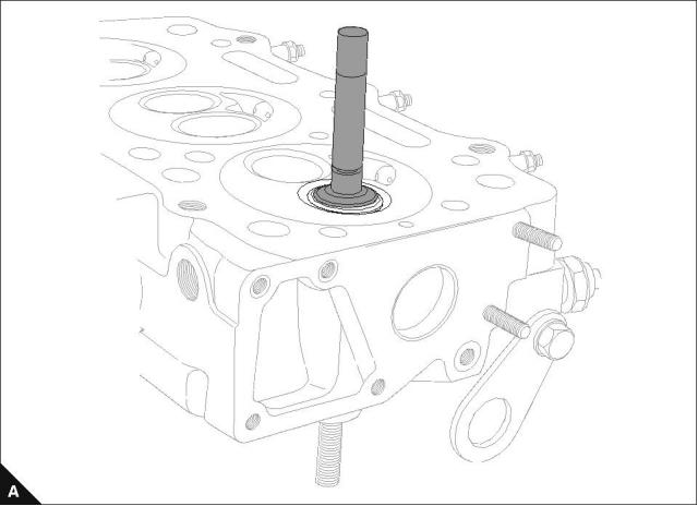
Valve seat width
To correct
Operation 3-20
If the contact width (B1) of the valve seat is more than service limit, check wear condition of the valve guide
first.
Using a seat cutter of 45° correct the seat.
Intake valve
Clearance mm (in)
Engine model
Standard
1,59 - 1,80 (0.0626 - 0.0709)
1,70 - 2,10 (0.0670 - 0.0830)
1,66 - 1,87 (0.0653 - 0.0736)
1,50 - 2,00 (0.0591 - 0.0790)
Service limit
2,5 (0,098) max
2,5 (0,098) max
2,5 (0,098) max
2,5 (0,098) max
102-05, 103-07
103-10
103-13, 103-15
104-19, 104-22
Exhaust valve
Clearance mm (in)
Engine model
Standard
1,59 - 1,80 (0.0626 - 0.0709)
1,70 - 2,10 (0.0670 - 0.0830)
1,66 - 1,73 (0.0653 - 0.0681)
1,94 - 2,16 (0.0764 - 0.0850)
Service limit
2,5 (0,098) max
2,5 (0,098) max
2,5 (0,098) max
2,5 (0,098) max
102-05, 103-07
103-10
103-13, 103-15
104-19, 104-22
45°
1
44
Workshop Manual, TPD 1377E, issue 4
This document has been printed from SPI². Not for Resale
![]()
![]()
![]()
![]()


3
100 Series
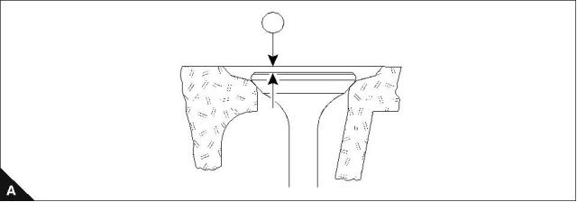
Valve depth
To correct
Operation 3-21
Special requirements
Depth (A1) mm (in)
Engine model
Standard
Service limit
1,8 (0.071) max
1,8 (0.071) max
1,8 (0.071) max
1,8 (0.071) max
102-05, 103-07
103-10
0,70 - 0,90 (0.0276 - 0.0354)
0,85 - 1,15 (0.0335 - 0.0453)
0,85 - 1,15 (0.0335 - 0.0453)
0,65 - 0,95 (0.0256 - 0.0374)
103-13, 103-15
104-19, 104-22
Rectify if the depth is more than the service limit.
1
Workshop Manual, TPD 1377E, issue 4
45
This document has been printed from SPI². Not for Resale
![]()
![]()
![]()
![]()

3
100 Series
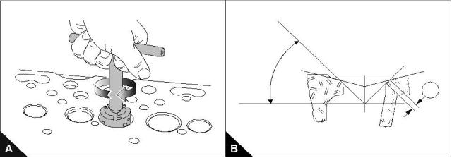
Valve seat contact face
Lapping
Operation 3-22
Correct valve seat contact using a valve lapping tool and lapping compound.
Note: When using a new cylinder head, obtain correct seat contact width and seat recess using the seat
cutter, then carry out a final lap.
46
Workshop Manual, TPD 1377E, issue 4
This document has been printed from SPI². Not for Resale
![]()
![]()
![]()
![]()
3
100 Series
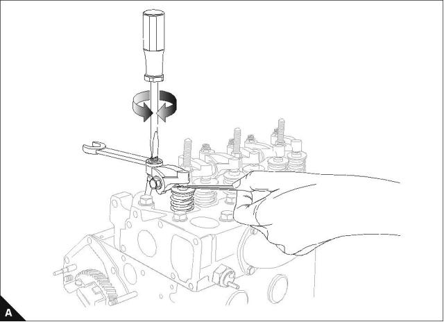
Valve tip clearance
To check
Operation 3-23
The valve sequence is viewed from the front of the engine.
Rotate the crankshaft clockwise when viewed from the front.
Adjust the clearance of both intake and exhaust valves to 0,2 mm (0.0078 in).
Note: Always adjust when the engine is cold.
Engine model
Valve overlap
Adjust valves
No.1 Cyl
No.2 Cyl
No.1 Cyl
No.2 Cyl
No.3 Cyl
No.4 Cyl
No.2 Cyl
No.1 Cyl
No.3 Cyl
3 and 4
1 and 2
3 and 6
2 and 5
1 and 4
1 and 2
5 and 6
7 and 8
3 and 4
2 Cylinder engines
3 Cylinder engines
4 Cylinder engines
Workshop Manual, TPD 1377E, issue 4
47
This document has been printed from SPI². Not for Resale
![]()
![]()
![]()
![]()

This page is intentionally blank
This document has been printed from SPI². Not for Resale
100 Series
4
Piston and connecting rod assemblies
4
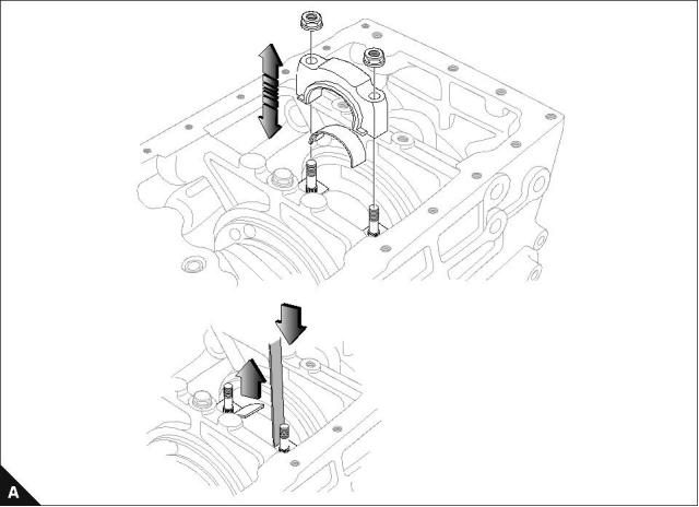
Big end bearing and cap
To remove and to fit
Operation 4-1
Special requirements
Torque Nm (lbf ft) kgf m
Clearance mm (in)
102-05, 103-07
23 (17) 2,3
32 (24) 3,2
52 (38) 5,3
Standard
Service limit
103-10
0,1 - 0,3 (0.004 - 0.012)
0,7 (0.276)
103-13, 103-15, 104-19, 104-22
Ensure that when the connecting rods are fitted an axial play (clearance) is provided.
During assembly apply a thin layer of clean engine lubricating oil to the crank pins with.
Notes:
Identify each rod/piston/cylinder pair on disassembly.
For emissions approved engines. The fuel adjustment screws must not be altered from the original settings.
For emissions approved engines. The maximum No Load Speed must be checked after assembly.
If new connecting rods are fitted, see Operation 3-13.
Workshop Manual, TPD 1377E, issue 4
49
This document has been printed from SPI². Not for Resale
![]()
![]()
![]()
![]()
![]()
![]()
![]()
![]()

4
100 Series
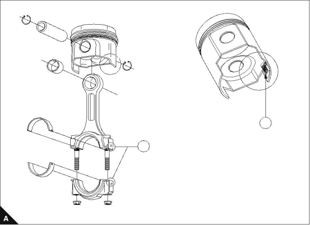
Piston and connecting rod
To dismantle and to assemble
Operation 4-2
Align Shibaura logo (A1) with stamped number on con rod.
Align numbers to match (A2).
1
2
50
Workshop Manual, TPD 1377E, issue 4
This document has been printed from SPI². Not for Resale
![]()
![]()
![]()
![]()
4
100 Series
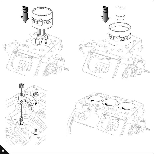
To fit
Operation 4-3
Special requirements
Torque Nm (lbf ft) kgf m
102-05, 103-07
103-10
23 (17) 2,3
103-13, 103-15, 104-19, 104-22
52 (38) 5,3
32 (24) 3,2
For positioning of connecting rod assembly refer to Operation 4-2.
Note: Pistons must be fitted with Shibaura name toward the fuel injection pump.
Workshop Manual, TPD 1377E, issue 4
51
This document has been printed from SPI². Not for Resale
![]()
![]()
![]()
![]()

4
100 Series
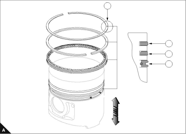
Piston and piston ring
To inspect
Operation 4-4
Any letters or marks on a surface of a ring (A1) will always be to the upper face.
The piston profile shows the No.1 ring (A2), No.2 ring (A3) and the oil scraper ring (A4).
1
2
3
4
52
Workshop Manual, TPD 1377E, issue 4
This document has been printed from SPI². Not for Resale
![]()
![]()
![]()
![]()
4
100 Series
To measure piston ring clearance
Operation 4-5
By use of feeler gauges, measure the clearance between the piston ring groove and ring. If the clearance
exceeds the service limit, renew the piston and rings.
102-05, 103-07, 103-10
Clearance mm (in)
Standard
103-13, 103-15, 104-19, 104-22
Clearance mm (in)
Piston ring
Service limit
Piston ring
Standard
Service limit
0,06 - 0,1
(0.0024 - 0.0039)
0,25
(0.0098)
0,07 - 0,11
(0.0028 - 0.0043)
0,25
(0.0098)
No. 01 ring
No. 01 ring
0,05 - 0,09
(0.0020 - 0.0035)
0,25
(0.0098)
0,04 - 0,08
(0.0016 - 0.0032)
0,25
(0.0098)
No. 02 ring
No. 02 ring
0,02 - 0,06
(0.0008 - 0.0024)
0,15
(0.0059)
0,02 - 0,06
(0.0008 - 0.0024)
0,15
(0.0059)
Oil control ring
Oil control ring
Workshop Manual, TPD 1377E, issue 4
53
This document has been printed from SPI². Not for Resale
![]()
![]()
![]()
![]()

4
100 Series
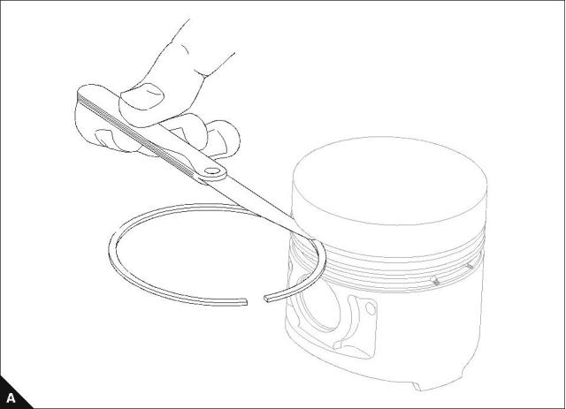
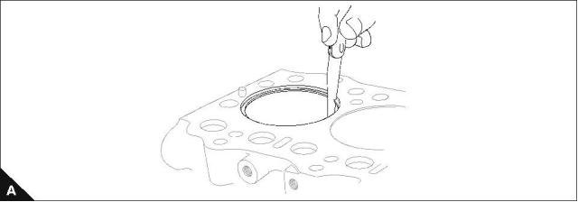
Piston ring and block
To inspect
Operation 4-6
Note: If the piston ring is worn or damaged, renew it.
Piston ring gap
Insert the rings into the cylinder at right angles to the cylinder bore and measure the gaps with a feeler gauge.
If the gap is more than the service limit, renew the ring.
102-05, 103-07
Gap mm (in)
Standard
103-10
Gap mm (in)
Standard
Piston ring
Service limit
Piston ring
Service limit
0,13 - 0,25
(0.0051 - 0.0100)
1,0
(0.040)
0,15 - 0,27
(0.0059 - 0.0106)
1,0
(0.040)
No. 01 ring
No. 01 ring
0,10 - 0,22
(0.0040 - 0.0087)
1,0
(0.040)
0,12 - 0,24
(0.0047 - 0.0094)
1,0
(0.040)
No. 02 ring
No. 02 ring
0,10 - 0,30
(0.0040 - 0.0120)
1,0
(0.040)
0,20 - 0,35
(0.0079 - 0.0138)
1,0
(0.040)
Oil control ring
Oil control ring
103-13, 103-15, 104-19, 104-22
Gap mm (in)
Piston ring
Standard
Service limit
0,20 - 0,35
(0.0079 - 0.0138)
1,0
(0.040)
No. 01 ring
0,20 - 0,40
(0.0079 - 0.0158)
1,0
(0.040)
No. 02 ring
0,20 - 0,40
(0.0079 - 0.0158)
1,0
(0.040)
Oil control ring
54
Workshop Manual, TPD 1377E, issue 4
This document has been printed from SPI². Not for Resale
![]()
![]()
![]()
![]()


免費熱線
400-100-8969???15088860848
400-100-8969???15088860848
機組銷售
0574-26871589? 15267810868
0574-26871589? 15267810868
配件銷售
0574-26886646? 15706865167
0574-26886646? 15706865167
維修熱線
0574-26871569 18658287286
0574-26871569 18658287286
手機端

微信公眾號